A power transformer uses a changing magnetic flux to couple electric power between windings at different voltages. The laminated steel core is central to that process: it carries most of the flux, limits magnetic losses and links all three phases.
Our first calculator focuses on balanced, three-phase, two-winding MV/LV transformers. It evaluates rated currents, winding quantities, vector group displacement, equivalent impedance magnitude and an explicitly simplified LV three-phase fault estimate.
What can we determine from a transformer nameplate?
Given rated three-phase apparent power (kVA), primary and secondary line-to-line voltages, short-circuit impedance uk% and the IEC vector group, we can calculate nominal line currents and the individual winding voltages and currents. The connection type matters for winding quantities, but not for the total rated current at a known three-phase kVA.
The transformer insulation/cooling selection — Cast Resin (dry type) or Oil-Immersed — is included for context. It does not silently change electrical ratings, uk% or allowed loading. Those values must come from the actual nameplate and manufacturer documentation.
How does the three-phase magnetic core work?
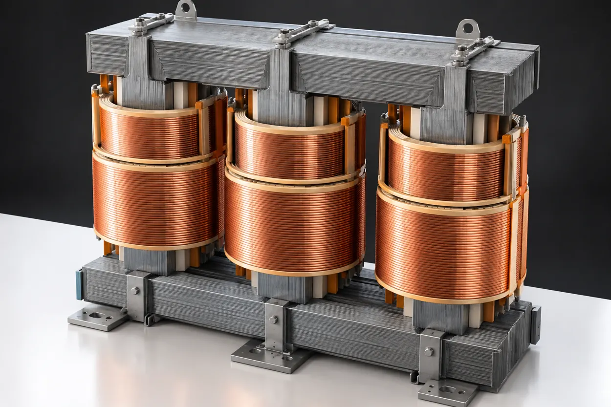
Most conventional three-phase distribution transformers use a three-limb core made from thin, insulated electrical-steel sheets. The vertical columns are called limbs; the horizontal connections are called yokes. Each limb carries windings for one phase, usually arranged concentrically around the steel.
An AC voltage applied to a primary winding creates alternating flux in its limb. The upper and lower yokes provide paths connecting the limbs; the flux in one limb is therefore coupled to the magnetic conditions in the others. In a balanced, ideal three-phase system, the instantaneous sum of the three limb fluxes is approximately zero:
Flux is not a physical substance flowing from the primary coil to the secondary. It describes the magnetic field passing through an area. The core provides a relatively low magnetic-reluctance path so that the same changing flux links both windings efficiently.
How does the transformer induce secondary voltage?
When the magnetic flux linking a winding changes, it induces an electromotive force (voltage). Faraday's law for a winding with N turns is:
The negative sign expresses Lenz's law: the induced action opposes the change causing it. Both primary and secondary windings link substantially the same core flux, so more turns correspond to more induced voltage. With approximately sinusoidal magnetic flux, the RMS voltage of a winding is:
Here f is frequency in hertz and Φmax is the peak magnetic flux in webers. This also explains why applying the same rated voltage at a lower frequency can raise flux density and drive the steel toward saturation.
At no load, the transformer still draws a relatively small magnetizing current to establish alternating flux, plus a component supplying its losses. When a load is connected, secondary current produces a magnetic effect opposed by an increase in primary load current, maintaining the core flux approximately set by the applied voltage and frequency.
Why is the core laminated rather than a solid steel block?
An alternating magnetic field induces circulating electric currents inside conductive steel. These eddy currents produce unwanted I²R heating. Building the core from thin, individually insulated electrical-steel laminations breaks up large current loops and greatly reduces those losses.
The core also dissipates energy during each cycle because its magnetic domains repeatedly change alignment. These are hysteresis losses. Special grain-oriented or other transformer-grade electrical steels help lower both types of magnetic loss.
Core-related power draw exists even when the secondary is disconnected; it is an important component of no-load loss P₀. In contrast, winding copper/aluminium resistive losses grow strongly with current and are often approximated as proportional to the square of load current.
Saturation, no-load current and transformer inrush
Steel is not infinitely magnetic. As flux density approaches the knee of the B–H magnetization curve, a further increase in magnetic field strength produces relatively little extra flux: the core moves toward magnetic saturation. Magnetizing current then rises disproportionately.
During energization, the switching instant and any residual magnetism can produce a transient flux offset. The transformer may draw a high, asymmetric magnetizing inrush current despite having no load on its secondary. The size and decay depend on the magnetic design, point-on-wave closing, residual flux and network impedance.
Protection systems therefore need to discriminate between inrush and true internal faults; differential relays commonly use inrush-restraint/blocking techniques, but settings must match the installed equipment and protection philosophy.
Cast Resin versus Oil-Immersed
Cast Resin · Dry-Type
Windings are typically encapsulated or insulated using solid insulation systems; cooling is usually by natural air (AN) or manufacturer-designed forced air (AF). The core and windings are not immersed in insulating liquid.
Relevant reference: IEC 60076-11 for dry-type power transformers.
Oil-Immersed
Core and windings are immersed in insulating liquid that provides electrical insulation and carries heat to radiators or tank walls. Typical cooling is ONAN, with fan-assisted ONAF on suitable models.
Relevant references: IEC 60076-1 and the oil-immersed loading guide IEC 60076-7, as applicable.
Both types obey the same induction and rated-current relationships. Their actual temperature-rise ratings, overload capacity, insulation clearances, maintenance and thermal behavior require separate type-specific data. Switching AN to AF or ONAN to ONAF does not automatically increase the kVA shown on the nameplate.
From rated kVA to line and winding values
The nominal current on each side of a balanced three-phase transformer comes from apparent power:
Cos φ is not needed because kVA is apparent power. The actual winding voltage and current depend on how each side is connected.
The ideal turn-voltage ratio corresponds to winding voltages, not simply the two nameplate line voltages:
For Dyn5 or Dyn11, HV is delta and LV is star: the HV winding sees the entire MV line-to-line voltage, while an LV phase winding sees 400/√3 V. Turns-ratio (TTR) test connections and instrument conventions must still be accounted for separately.
Vector groups: why Dyn5 is not Dyn11
Dyn5 — our default
D: HV delta connection.
y: LV star connection.
n: LV neutral brought out.
5: LV line phasor at clock position 5, equivalent to lagging the HV reference by 150°.
For comparison, Dyn11 uses the same delta/star connections and neutral arrangement but places the LV line phasor at clock 11: leading by 30°.
The clock positions indicate phase displacement, not the physical direction of transformer rotation. Two transformers with differing vector groups generally must not be paralleled without an engineered assessment; circulating current and phase mismatch are serious hazards.
The calculator also offers Dyn1, Dyn7, Yyn0, Dd0 and selected YN/d configurations. It reports neutral availability and winding quantities based on the selected winding connections. It does not calculate zero-sequence fault impedance, actual terminal polarity diagrams or harmonic circulation.
What does short-circuit impedance tell us?
The nameplate short-circuit impedance uk% describes the magnitude of the transformer equivalent impedance in per unit, expressed as a percentage on rated base values. On the LV side:
A simple initial symmetrical fault estimate at the LV terminals, assuming an infinite upstream short-circuit source, is:
This is a transformer-only upper-style screening estimate, not a guaranteed installation maximum and not a complete IEC 60909 result. Network voltage factors, upstream impedance, source configurations, correction factors, contributions from motors and other sources, fault X/R, tap settings and connection impedance can change an actual fault study.
The output should not be used alone to select a circuit breaker's making/breaking capacity or to approve LV switchgear withstand ratings.
1,600 kVA · 20/0.4 kV · Dyn5 · uk = 6%
Assume a cast-resin, AN-cooled, three-phase transformer with 1,600 kVA, HV 20 kV, LV 400 V, IEC group Dyn5 and uk 6%. The numbers below are computed by the same engine as the calculator.
Engineering interpretation: The nominal LV current is relevant when choosing feeder conductors or initial LV busbar arrangements. The fault estimate highlights the need for a real short-circuit/protection study, but cannot on its own certify a switchboard or breaker.
What we must verify during design and testing
Collect the manufacturer's nameplate, tap position, rated voltages and cooling designation. For protection and switchgear, obtain actual source and transformer fault data and run an appropriate IEC 60909 study rather than relying on the transformer-only estimate.
For field tests such as TTR, winding resistance, insulation resistance and vector-group checks, use the correct terminal connections and test procedure. A physical turns-ratio test instrument may show a different representation from the line-to-line voltage ratio, depending on how it excites and senses the windings.
Detailed losses, efficiency, tap-changer performance, inrush magnitude, overload capacity, temperature rise, zero-sequence impedance and earth-fault behaviour are intentionally not computed in this first version.
Avoid these transformer calculation errors
Rated currents follow directly from kVA and line voltage; cos φ is not an input.
For delta/star transformers, line-to-line ratio and per-winding ratio differ by √3.
Equal rated currents do not imply equal phase displacement or suitable paralleling.
Use the actual transformer test/nameplate uk%, not a generic default.
The utility source, correction factors, operating configuration and contributions matter.
Only a manufacturer-designated and verified AF/ONAF rating permits different loading.
Standards and technical references
IEC 60076-1 (general transformer principles and nameplate quantities), IEC 60076-11 (dry-type transformers), IEC 60076-7 (oil-immersed loading guidance), IEC 60076-12 (dry-type loading guidance), and IEC 60909-0 (short-circuit calculations in three-phase AC systems). Always check editions and applicable national adoption when designing an actual installation.
For detailed technical reading, consult the Schneider Electric Electrical Installation Guide and the IEC Webstore for official standard publications. KiloVolt supplies educational approximations; it is not a standards certification body.